WS2815 is an intelligent control LED light source that the control circuit and RGB chip are integrated in a package of 5050 components. Its internal includes intelligent digital port data latch and signal reshaping amplification drive circuit.
Dual-signal wires version, signal break-point continuous transmission. Any pixel’s failure won't affect signal transfer and total emitting effect. The data transfer protocol uses a single NZR communication mode. After the pixel power-on reset, the DIN port receives data from the controller, the first pixel collects initial 24bit data then sent to the internal data latch, the other data which
reshaping by the internal signal reshaping amplification circuit sent to the next cascade pixel through the DO port. After transmission for each pixel, the signal to reduce 24bit. Every pixel adopts auto-reshaping transmit technology, making the pixel cascade numbers are not limited to the signal transmission, only relate to the speed of signal transmission.
The BIN receives the data signal, and then compare the data with the DIN side after phagocytosis of 24bit data, if DIN do NOT receive the signal, then switching to BIN for receiving the input signal, which ensures that any the IC's damage does not affect the signal cascade transmission and make the BIN in state of receiving signal until restart after power-off.
Refresh Frequency updates to 2KHz, Low Frame Frequency, and no Flicker appear in HD Video Camera.
RESET time>280μs, it won’t cause the wrong reset while interruption, it supports the lower frequency and inexpensive MCU.
Integrated circuit chips enable the circuit control simpler, neater and more reliable while NO extra components needed.
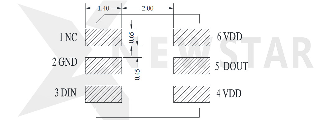
Mechanical Dimensions
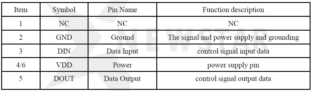
PIN Configuration
PIN Function
Absolute Maximum Ratings
Electrical Characteristics (TA=-20~+70℃, VDD=4.5~5.5V, VSS=0V)
Switching Characteristics (TA=-20~+70℃, VDD=4.5~5.5V, VSS=0V)
LED Characteristics
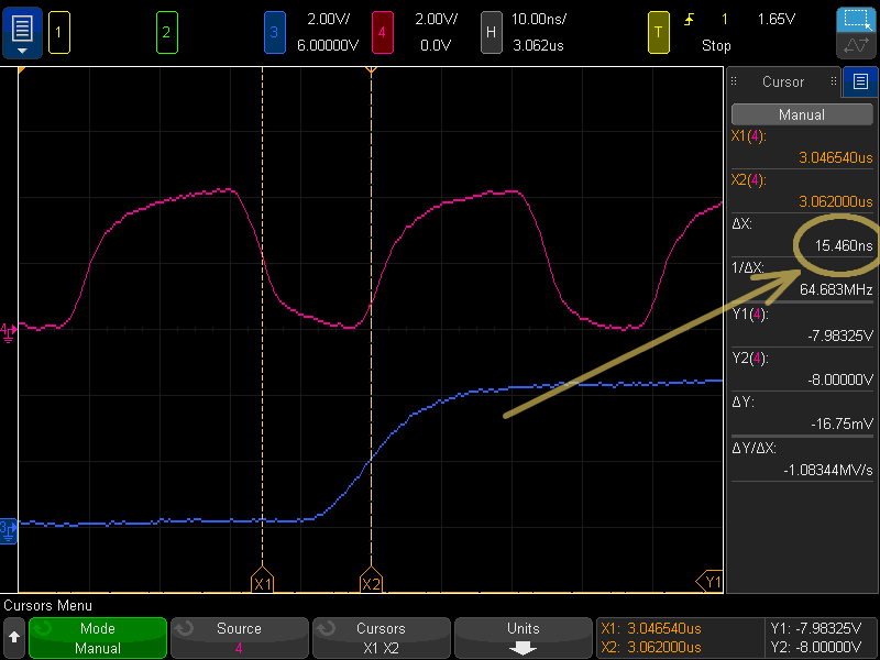
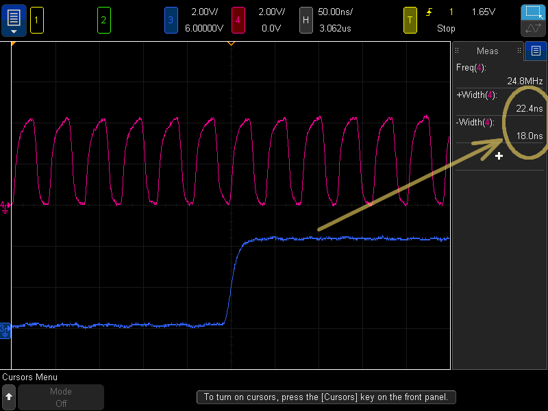
Data Transfer Time
Data Transmission Method
Note: D1 is the data from MCU, and D2, D3, D4 are from Cascade Circuits
The composition of 24bit data
Note: Data transmit in order of GRB, high bit data is first.
Typical application circuit
1. Recommended application circuit
Remarks: C1 is bypass filter capacitor, its value of 100NF.
2. For complicated wiring & space-saving
So what is GS8208?
The GS8208 is a 3-channel constant current LED driver with resumable data transfers and internal display patterns. There are three open-drain constant current outputs, with a built-in PWM of grayscale. The range of input power is from 9VDC to 15VDC, and voltage-endurance of LED port is +12VDC. there is a built-in 12bits GAMMA correction module. PWM maximum refresh frequency is 8kHz. The GS8208 use the e-Rz (extended return to zero code) as the signal transmission mode, which can control the output current channel by channel and cascade infinitely. GS8208 provides two signal data input as redundant control, which ensures the transmission of the signal if any single chip damages. In the absence of signal input, GS8208 displays the built-in display patterns that are suitable for those applications without a controller. there is the built-in power-on the power-off protection in the driver, which can enhance the service life of the chip. It also has the automatic test function while power on, which is convenient for the customer to test. The GS8208 provides SOP8 packaging, the working environment is from -° 40° C to + 85C.
Features
-12V operating supply voltage with 7805 module inside
-Default 17.5mA constant current output, the minimum is 11mA.
-Use e-Rz code, serial data frequency 800kHz.
-8bits data transfer, 12bits build-in GAMMA correction of PWM display.
-Built-in PWM technology, supports 8kHz PWM refresh rate.
-With resumable data transfer function, single chip damage does not infect data transmission.
-Built-in automatic test mode, power-on and power-off protection.
-ESD: 2KV.
Typical Applications:
Block Diagram
PIN
PIN Description
Equivalent Circuits of Input and Output
Maximum Ratings
(1) Stresses above there ratings may cause permanent damage. Exposure to absolute maximum condition for extended periods may degrade device reliability. These are stress ratings only and functional operation of the device at these or any other condition beyond those specified is not supported.
(2) All voltage values are with respect to the ground terminal.
Electrical Characteristics
Switching Characteristics
Typical Application
Data Format
GS8208 adopts the extended return zero code (e-RZ) data transmission mode, 8bits data for a single channel, each IC support 3 channel for display. The transmission data is filtered internally to support the data anti-jitter function. The extension type is compatible with traditional RZ code. So it is suitable for most of RZ code controller in the market.
Single code with 1:3 duty cycle and a standard 800kHz transmission speed. The maximum frequency can reach 1MHz. GS8208 re-code the data before transmission. Data delay is less than 0.7us from chip to chip, meets the dynamic image needs.
Dual Channel redundant control
Dual channel redundant control can be used to effectively avoid the failure of any single device damage, and reduce the damage rate of driving system to one millionth. The SDI signal is used as the default transmission channel while the system is power on. The transmission channel priority is switched between SDI and SDI2 when the transmission data is abnormal. The device will choose the clear transmission channel after data detection.
When the external control data is transmitted, SDI used the 1-24bits received data as the display data, meanwhile SDI2 will discard the 1-24bits data and use 25-48bits data as the display data.
Dual Channel status testing during production
In the production process, any one of the abnormal data channel will not affect display because the chip uses dual SDI input. it is difficult to detect the problem data channel during the production process, which may cause the dual channel is equivalent to a single channel.
In order to avoid this situation, the status of the data channel can be detected by using the test controller in the external control situation. While any channel appears weld, short, open or other abnormal communication, the chip will display in white to facilitate the detection of the problem position.
Working principle of series structure LED controller
it is RGB LED series structure. Power supply voltage is 12V, and the LED constant current is 18mA. Different to the parallel architecture of 5v power supply and 54mA driver current, the series architecture can provide a better driver ability. The new architecture's total driver current is only 1/3 of the original one and Vds=4V. The power loading ability is better.
In the series structure mode, when the internal MOS paralleling with the LED is open, the current flow into the LED and the LED lights. When the internal MOS paralleling with the LED is short, the current flow into the MOS device and the LED close. Switching the MOS device by PWM signal can lights on or off the LED.
Working principle of series structure LED controller
In order to prevent the large power interference from the LED switching, reduce the power circuit voltage fluctuations, GS8208 has built-in output hysteresis function. OUT1, OUT2, OUT3 will work in accordance with 80ns interval sequence, to improve the system's anti-jamming performance. Meanwhile, the current peak output stagger will reduce the system EMI radiation, to meet environmental requirements.
MPWM (multi-PWM)
In order to increase the refresh rate of PWM output, MPWM adopts a unique method of dispersibility to distribute the periodic N in the display time, as shown in the figure below. GS8208 adopts MPWM technology, and the PWM refresh rate increases to 8kHz, which shows the gentle effect and does not affect the accuracy of output current.
MPWM (multi-PWM)
GS8208 gets into RGB test mode right after power on. If the device does not receive the external display data for a long time, the chip will go into the built-in display patterns mode. The pattern on a total of six categories of 32 series, including integral color jump, integral color gradient, meteors, waves, colorful gradient, color jump of water circulation. It is 10 minutes about, and the image refresh frequency is 100hz.
Under the internal display mode, the first chip's SDI/SDI2 needs to be connected to GND.
Power dissipation
When all the three output channels are turned on, the practical power dissipation is determined by the following equation:
(Vout represents the output terminal voltage when the current is turned on; Duty represents the ratio of the time at which the current is turned on)
PD(practical) VccxIccVoutA2xIoutA2xDutyA2...VoutD0xIoutD0xDutyD0
In secure operation conditions, the power consumption of an integrated chip should be less than the maximum permissible power dissipation which is determined by the package types and ambient temperature. The formula for maximum power dissipation is described as follows:
The PD (max) declines as the ambient temperature rises. Therefore, suitable operating conditions should be designed with caution according to the chosen package and the ambient temperature. The following figure illustrates the relation between the maximum power dissipation and the ambient temperature of the SOP8 package.
If you don't know which one is more suitable to you, please contact us.
Newstar
www.newstar-ledstrip.com