Translate

显示标签为“APA102C”的博文。显示所有博文

2018年10月30日星期二

NS107S, the upgrade of APA107 LED, much better than Taiwan APA102

NS107S is the upgrade type of APA107 LED
PWM refresh rate >26kHz, Oscillator Frequency is 30MHz


NS107S LED Product Overview
NS107S RGB LED Chip is a type ic for the three-color RGB Diming control strip and string ,This ic using the CMOS process to provide three-color RGB LED output driver to adjust the output with 256 gray scale and 32 brightness adjustment, NS107S Pixel diodes with 2 signal output way , one is clock ,another is data, the clock and data is synchronizated, so that the crystal cascade piece of output movement is sychronizated.

RGB NS107S LED Strip

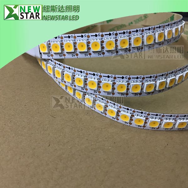
White NS107S LED Strip

NS107S LED Feature
CMOS process,low voltage ,low consumption
Synchronization of two-lane
Choose positive output or negative RGB three-color LED output
8 bit(256 level) color set ,5bit(32 level) brightness adjustment
Build-20ma constant current output
With self-detection signal build in support for continuous oscillation PWM
output ,can be maintained static screen


NS107S LED Main Application Field:
● Full color LED string light, LED full color module, LED super hard and soft lights, LED guardrail tube, LED appearance/scene lighting
● LED point light, LED pixel screen, LED shaped screen, a variety of electronic products, electrical equipment etc..

NS107S LED Mechanical Product Size (unit mm):


NS107S LED Application Circuit:

More details, pls contact us.

NEWSTAR LED
info@newstarleds.com
www.newstar-ledstrip.com

2017年4月6日星期四

APA107 LED chip, the upgrade of APA102C, better and cheaper than APA102 SK9822

APA107 will be upgraded soon, the PMW can be 26-28kHz

TEST RESULT
 Our customer's test result: "The logarithmic curve of the APA107 starts more logic in the beginning:
The APA102 gave nearly NO intensity in the very beginning. (This gave no nice display)Now there is some small brightness in the beginning of the APA107 curve. What is very good!!!! "

APA107 LED Product Overview
APA107 is a type ic for the three-color RGB Dimming control strip and string, This IC using the CMOS process to provide three-color RGB LED output driver to adjust the output with 256 grayscale and 32 brightness adjustment, APA107 with 2 signal output way , one is clock ,another is data, the clock and data is synchronizated ,so that the crystal cascade piece of output movement is sychronizated .

RGB APA107 LED Strip
White APA107 LED Strip

APA107 LED Feature
CMOS process,low voltage ,low consumption
Synchronization of two-lane
Choose positive output or negative RGB three-color LED output
8 bit(256 level) color set ,5bit(32 level) brightness adjustment
Build-20ma constant current output
With self-detection signal build in support for continuous oscillation PWM
output ,can be maintained static screen


APA107 LED Main Application Field:
● Full color LED string light, LED full color module, LED super hard and soft lights, LED guardrail tube, LED appearance/scene lighting
● LED point light, LED pixel screen, LED shaped screen, a variety of electronic products, electrical equipment etc..

APA107 LED Mechanical Product Size (unit mm):


APA107 LED PIN Description

APA107 LED Application Circuit:

APA107 LED Block diagram:
(Absolute Maximum Rating)
Supply voltage -------------- -0.3-6.0V
Input voltage---------------- VSS-0.3 to VDD +0.3V
Operating temperature---------------- -40 to +70℃
Storage temperature------------------- -50 to +125℃
Note: Stress above those listed may cause permanent damage to the
devices

APA107 LED Electrical Characteristic:

APA107 LED Function Description:
  (1) cascading data structure
       Tandem N-LED:
Global bit:5 bit (32 level) brightness setting,while controlling R,G,B three-color
constant current output value,if set the global bit for the 10000( 16/31 ) is the output
current is half again the original PWM settings
APA107 LED PWM input and output signals Relations

(2). The number of pixel per second sent to the CKI frequency (FCKI) minus the Start
Frame bit divided by the number 40 the number of LED Frame bit 32, if the CKI
frequency(FCKI) to 512KHZ. The pixel number (512000-40)/32=15998, if the 50
second update Views can be connected in series LED number 15998/50=319. To
increase the number of cascaded IC CKI frequency
(3).POLAR to empty ,R,G,B for the negative output;POLAR access VSS ,R,G,B is
positive output
(4).VEN: self-detection
DATA field to the middle of 3 bit is B,G,R in the MSB of the opposite
phase, otherwise regarded as invalid data. VEN close to the empty when the
self-detection; when VEN VSS then activated self-detection
(5).CSEL to empty when the CKO and CKI,RP:CSEL connected with VSS when the
CKO compared with CKI.

APA107 LED SMD:
Compare with APA102C SK9822,  the advantage of APA107,

1, Intelligent reverse connect protection, the power supply reverse connection does not damage the IC.
2, The control circuit and the LED share the only power source.
3, Control circuit and RGB chip are integrated in a package of 5050 components, form a complete control of pixel point.
4, Built-in signal reshaping circuit, after wave reshaping to the next driver, ensure wave-form distortion not accumulate.
5, Built-in electric reset circuit and power lost reset circuit.
6, Each pixel of the three primary color can achieve 256 brightness display, completed 16777216 color full color display, and scan frequency not less than 400Hz/s.
7, Cascading port transmission signal by single line.
8, Any two point the distance more than 5m transmission signal without any increase circuit.
9, When the refresh rate is 30fps, cascade number are not less than1024 points.
10, Send data at speeds of 800Kbps. 
11,The color of the light were highly consistent, cost-effective.. 
Applications 
12, Full-color module, Full color soft lights a lamp strip.
13, LED decorative lighting, Indoor/outdoor LED video irregular screen. 

More details, pls contact us.
NEWSTAR LED CO., LIMITED
info@newstarleds.com
www.newstar-ledstrip.com
2017年3月21日星期二

The difference with APA102 and APA102c

There are two versions of the market, the APA102 and the APA102C, as shown below.
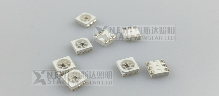
The APA102C comes in a package very similar to the WS2812, while the APA102 comes in a package with an increased metallization area to improve heat conduction. The APA102 is more expensive, possibly owed to the more complicated package. So far, I was only able to investigate the low-cost version, the APA102C.

The controller IC was designed by a Taiwanese company, Newstar LED. Unfortunately, they do not have a lot of detailed information on their website. But they were nice enough to send me the original data sheet upon request. I mirrored the datasheets here: APA102 and APA102C
I contrast to the very timing-sensitive one-wire protocol of the WS2812, the APA102 uses a standard two-wire SPI protocol – one clock line and one data line. Each LED has two inputs and two outputs which can be daisy chained. At the first sight, this may seem wasteful, but it has the advantage of being supported by standard microcontroller periphery and it is insensitive to timing variations. Due to the critical timing requirement, it is not possible to control the WS2812 from SOCs with multitasking operating systems, such as the Raspberry Pi. This should not be an issue with the APA102. Furthermore, the data can be transferred at an almost arbitrary clock rate. I was able to control the LEDs with 4 MHz SPI clock without any hitch. It appears that the maximum speed is mainly limited by the parasitics of the wiring. The data format is shown below.
Each update consists of a start frame of 32 zeroes, 32 bits for every LED and an end frame of 32 ones.  I am not sure what the “End Frame” is good for since its encoding is indistinguishable from a LED set to maximum brightness and will simply be forwarded to the next LED. In my experiments, omitting the end frame did not have any impact.
One interesting addition is the “global” field for each LED, which allows controlling the brightness of the LED in 32 steps from 0 to 31. When trying different parameters, I was quite surprised to observe that the LEDs did not show any visible pulse-width-modulation (PWM) flicker at all when the global brightness was set to 31. This is quite different from the WS2812, which shows visible PWM flicker when moving the LEDs.
Interestingly, the APA102 started to flicker once I set the global brightness to 30 or below. To understand what was going on, I hooked up my scope to the power rails. When the LEDs are turning on, they draw significantly higher current which leads to a drop in voltage across the power rails. I previously used a similar method to investigate the inner workings of candle flicker LEDs.
The picture above shows the current modulation for RGB=255,255,255 and the global brightness set to 16 (50%). The pulse width modulation is clearly visible in the voltage signal at a frequency of 580 Hz, very similar to the 430 Hz of the WS2812.

Next, I set the RGB value to 128,128,128 and kept the global brightness at 50%. The result is shown above. Two PWM modulation schemes are superimposed in this configuration. The global brightness is still modulated at ~582 Hz, while the RGB value is modulated at an approximately 32 times higher frequency, 19.2 kHz. This frequency is significantly above the flicker fusion threshold, even when moving the LED around, leading to an apparent constant brightness.
The very high PWM frequency is a pretty nice feature of these LEDs. In combination with the higher update speed due to the SPI interface, they should be much better suited for persistence-of-vision applications than the WS2812.
In summary, the APA102 show significant promise compared to the de-facto standard WS2812:
  • They can be controlled with a standard SPI interface. No critical timing required and much faster than the one wire protocol.
  • They have an extremely high PWM frequency, allowing flicker-free POV applications.
  • They are available in a special package with better heat sinking.
NEWSTAR LED CO., LIMITED 
www.newstar-ledstrip.com

2016年12月6日星期二

APA102C compare with SK6812 LED Strips

APA102/APA102C LED strips are controlled through an SPI protocol on the data and clock input lines. The protocol is documented in the APA102C datasheet (1MB pdf), but we describe it below with some modifications that we have found to work better.

The default, idle state of the clock signal line is low, and the data signal is read on each rising edge of the clock. To update the LED colors, you need to toggle the clock line while driving the data line with the value of each bit to send; this can be done through software (bit-banging), or it can be handled by a hardware SPI peripheral in a microcontroller. There is no minimum clock frequency, although using a lower frequency means that it will take longer to update the entire sequence of LEDs (especially when controlling a long strip or many strips are chained together), so you will probably want to use the fastest practical clock speed to get the best update rate.


APA102C control signal timing diagram.
The data for each LED is encoded as a sequence of 32 bits (4 bytes) called an LED frame. The first three bits of the LED frame should be ‘1’. The next 5 bits are a “global”, colour-independent brightness value (0–31) that is applied equally to all three color channels. The remaining 24 bits are the color values, in BGR (blue-green-red) order. Each color value uses 8 bits (0–255). The most significant bit of each value is transmitted first. The first LED frame transmitted applies to the LED that is closest to the data input connector, while the second color transmitted applies to the next LED in the strip, and so on.

To update all the LEDs in the strip, you should send a “start frame” of 32 ‘0’ bits, then a 32-bit “LED frame” for each LED, and finally an “end frame”. If you send fewer LED frames than the number of LEDs on the strip, then some LEDs near the end of the strip will not be updated.


The APA102/APA102C datasheet recommends that the end frame be composed of 32 ‘1’ bits, but we have found this does not work reliably in certain situations and can sometimes lead to glitches. This can be avoided by using an end frame that consists of at least (n–1)(n–1) extra clock edges, where nn is the number of LEDs, with ‘0’ on the data line. It is often easiest to round up to a multiple of 16 clock edges so that you are counting bytes instead (there are 2 clock edges in a bit and 8 bits in a byte); you would, therefore, send ((n–1)/16)((n–1)/16) bytes (rounded up to the next whole number). For a more detailed explanation, see the comments in the source code of our APA102/APA102C Arduino library, discussed below.


APA102C data format.

For example, to update all 30 LEDs on a 1-meter strip, you should send a 32-bit start frame, thirty 32-bit LED frames, and a 16-bit end frame, for a total of 1008 bits (126 bytes). If multiple strips are chained together with their data connectors, they can be treated as one as longer strip and updated the same way (two chained 1-meter strips behave the same as one 2-meter strip).

Each RGB LED receives data on its data input line and passes data on to the next LED using its data output line. The update rate is generally limited only by the speed of the controller; our Arduino library below can update 60 LEDs in about 1.43 milliseconds, so it is possible to update nearly 700 LEDs at 60 Hz. However, constant updates are not necessary; the LED strip can hold its state indefinitely as long as power remains connected.

Note: The minimum logic high threshold for the data and clock signals is 3.5 V, so you should use level-shifters if you want to control these strips from 3.3 V systems. It might be possible to control them with 3.3 V signals directly, but using the strip out of spec like this could lead to unexpected problems.

Comparison with SK6812 LED Strips

Like the APA102/APA102C, the SK6812 used in some of our LED strips also combines an RGB LED and driver into a single 5050-size package. However, while the SK6812 uses a one-wire control interface with strict timing requirements, the APA102/APA102C uses a standard SPI interface, with separate data and clock signals that lets it accept a wide range of communication rates; the trade-off is that two I/O lines are required to control it instead of just one.
The APA102/APA102C provides a 5-bit color-independent brightness control that is not available on the SK6812. This feature can be used to vary the intensity of each pixel without changing its color, and it enables much subtler variations at the low end of the LEDs’ brightness range.
In addition, the APA102/APA102C uses a much higher PWM (pulse-width modulation) frequency for controlling each color channel—about 20 kHz, compared to around 1.2 kHz on the SK6812. As a result, APA102/APA102C LEDs can be less prone to flickering when recorded with a camera and are more suited to applications like persistence-of-vision (POV) displays. (The color-independent brightness is modulated separately at about 600 Hz).
The SK6812 has voltage-independent color and brightness over a wide voltage range. This makes it a good choice for installations with power wires longer than a few meters.
Another advantage of the SK6812 is that all the LEDs in a chain are updated at nearly the same time. The LEDs update the color they are displaying when they see a long enough low period on the data line. The transmission delay from one LED to the next is at most 0.5 μs, so if you were controlling a display of 450 LEDs, they would all be updated within a fraction of a millisecond. The APA102/APA102Cs update the displayed color as soon as their next color is received. Using our Arduino library, it would typically take over 10 ms to send colors to a chain of 450 APA102/APA102Cs, which means that some LEDs would get updated 10 ms before other LEDs in the same chain. This makes the SK6812 a good choice for installations with a large number of LEDs where update latency is a concern.
For more information about the ICs, see the SK6812 datasheet and APA102C datasheet 
While our SK6812 strips and APA102/APA102C strips are physically very similar, they are not functionally compatible with each other. The easiest way to tell them apart is to look at the strips’ end connectors and the connections between each LED segment: SK6812 strips have three connections (power, data, and ground), while APA102/APA102C strips have four (power, clock, data, and ground).

More details, please contact us.
Newstar LED co., limtied
www.newstar-ledstrip.com